
Category: Laptop Repair and Service
Contents of this article
- Disassembling procedure
- Battery pack checking
- Key board and INPUT check
- Memory check
Acer TravelMate ALPHA -550
Running
Diagnostics Program
1. BIOS Re-flash
Insert CD-Disk and floppy disk then boot from floppy disk drive to BIOS re-flash.
1. BIOS Re-flash
Insert CD-Disk and floppy disk then boot from floppy disk drive to BIOS re-flash.
2. Parallel Port Test
Insert PIO loopback ot parallel port for test.
Insert PIO loopback ot parallel port for test.
3. RTC, FDD Test
Insert diskette to floppy disk drive for test.
Insert diskette to floppy disk drive for test.
4. Thermal Test
5. CD-ROM Test
First test left channel, if you hear sounds then press ENTER key to test right channel.
First test left channel, if you hear sounds then press ENTER key to test right channel.
If you hear sounds then press “P” key to pass this item.
6. Batter Charge Test
Plug the AC adapter to the system for test.
Plug the AC adapter to the system for test.
7. Video mode Test
Check the RGB video mode display quality.
8. T/P Mouse Test
Check the RGB video mode display quality.
8. T/P Mouse Test
9. FAN Test
Check if the fan has turned on with feathers.
Check if the fan has turned on with feathers.
10. LAN Test
1. Keyboard Test
Press all keys according to this order--from left to right and from up to down to test each key’s function. If pass
then press CTRL + Break to continue the next test.
Press all keys according to this order--from left to right and from up to down to test each key’s function. If pass
then press CTRL + Break to continue the next test.
12. 32bit Syscard Test
Insert two pieces of Syscard (Card bus) into PCMCIA slots for test. Check travel card if found error code on the
card then record to SFIS and travel card else affix QC seal on the travel card.
Insert two pieces of Syscard (Card bus) into PCMCIA slots for test. Check travel card if found error code on the
card then record to SFIS and travel card else affix QC seal on the travel card.
System
Check Procedures External Diskette Drive Check
Do the following to isolate the problem to a controller, driver, or diskette. A write-enabled, diagnostic diskette is required.
NOTE: Make sure that the diskette does not have more than one label attached to it. Multiple labels can cause damage to the drive or cause the drive to fail.
Do the following to select the test device. See “System Diagnostic Diskette” on page 45 for details.
1. Boot from the diagnostics diskette and start the diagnostics program
2. See if FDD Test is passed as the program runs to FDD Test.
3. Follow the instructions in the message window.
If an error occurs with the internal diskette drive, reconnect the diskette connector on the system board. If the error still remains:
1. Reconnect the external diskette drive/DVD-ROM module.
2. Replace the external diskette drive/CD-ROM module.
3. Replace the main board.
External
CD-ROM Drive Check
Do the following to isolate the problem to a controller, drive, or CD-ROM. Make sure that the CD-ROM does not have any label attached to it. The label can cause damage to the drive or can cause the drive to fail.
Do the following to select the test device:
1. Boot from the diagnostics diskette and start the diagnostics program.
2. See if CD-ROM Test is passed when the program runs to CD-ROM Test.
3. Follow the instructions in the message window. If an error occurs, reconnect the connector on the System board. If the error still remains:
1. Reconnect the external diskette drive/CD-ROM module.
2. Replace the external diskette drive/CD-ROM module.
3. Replace the main board.
Keyboard or Auxiliary Input Device Check
Remove the external keyboard if the internal keyboard is to be tested. If the internal keyboard does not work or an unexpected character appears, make sure that the flexible cable extending from the keyboard is correctly seated in the connector on the system board.
If the keyboard cable connection is correct, run the Keyboard Test. See “System Diagnostic Diskette” on page 45 for details.
If the tests detect a keyboard problem, do the following one at a time to correct the problem. Do not replace a non-defective FRU:
1. Reconnect the keyboard cables.
2. Replace the keyboard.
3. Replace the main board.
The following auxiliary input devices are supported by this computer:
Numeric keypad
External keyboard
If any of these devices do not work, reconnect the cable connector and repeat the failing operation.
Memory Check
Memory errors might stop system operations, show error messages on the screen, or hang the system.
1. Boot from the diagnostics diskette and start the doagmpstotics program
2. Go to the diagnostic memory in the test items.
3. Press F2 in the test items.
4. Follow the instructions in the message window.
NOTE: Make sure that the DIMM is fully installed into the connector. A loose connection can cause an error. Power System Check To verify the symptom of the problem, power on the computer using each of the following power sources:
1. Remove the battery pack.
2. Connect the power adapter and check that power is supplied.
3. Disconnect the power adapter and install the charged battery pack; then check that power is supplied by the battery pack.
Check
the Battery Pack
To check the battery pack, do the following:
From Software:
1. Check out the Power Management in control Panel
2. In Power Meter, confirm that if the parameters shown in the screen for Current Power Source and Total
Battery Power Remaining are correct.
3. Repeat the steps 1 and 2, for both battery and adapter.
4. This helps you identify first the problem is on recharging or discharging.
From Hardware:
1. Power off the computer.
2. Remove the battery pack and measure the voltage between battery terminals 1(+) and 6(ground). See the following figure
3. If the voltage is still less than 7.5 Vdc after recharging, replace the battery.
To check the battery charge operation, use a discharged battery pack or a battery pack that has less than 50% of the total power remaining when installed in the computer. If the battery status indicator does not light up, remove the battery pack and let it return to room temperature.
Re-install the battery pack.
If the charge indicator still does not light up, replace the battery pack. If the charge indicator still does not light up, replace the DC/DC charger board. Touchpad Check
If the touchpad doesn’t work, do the following actions one at a time to correct the problem. Do not replace a non-defective FRU:
1. After rebooting, run Tracking Pad PS2 Mode Driver. For example, run Syn touch driver.
2. Run utility with the PS/2 mouse function and check if the mouse is working.
3. If the the PS/2 mouse does not work, then check if the main board to switch board FPC is connected O.K.
4. If the main board to switch board FPC is connected well, then check if the FCC on touch pad PCB connects properly.
5. If the FFC on touch pad PCB connects properly, then check if LS851 JP1 Pin6=5V are pulese. If yes, then replace switch board. If no, then go to next step.
6. Replace touch pad PCB.
7. If the touch pad still does not work, then replace FPC on Track Pad PCB.
After you use the touchpad, the pointer drifts on the screen for a short time. This self-acting pointer movement can occur when a slight, steady pressure is applied to the touchpad pointer. This symptom is not a hardware problem. No service actions are necessary if the pointer movement stops in a short period of time.
DISASSEMBLING PROCEDURE
Removing the HDD Module/Thermal Module/CPU and DVD-ROM
1. Remove the two screws of the HDD module, then remove the HDD module from the logic lower.
1. Remove the two screws of the HDD module, then remove the HDD module from the logic lower.

2. Unscrew the three screws on the ram door. Then remove
the ram door. Next, disconnect the thermal
connector. Then, remove the four screws on the thermal module and remove the thermal module.
connector. Then, remove the four screws on the thermal module and remove the thermal module.

3. Use the CPU fixture and the flat-bladed screw driver
to remove the CPU.

4. Remove the screw on the DVD-ROM bracket and push the
DVD-ROM bracket. Then remove this module.

Removing the LCD Module/the Keyboard and the System
Window Removing the LCD Module
1. Remove the two (one on each side) screws holding the LCD stripe cover. Then prize the stripe cover with
the plastic flat-bladed tool.
2. Unscrew the four screws (two on each side) holding the LCD module to the main unit. Then, Disconnect LCD FPC and remove the LCD module.
1. Remove the two (one on each side) screws holding the LCD stripe cover. Then prize the stripe cover with
the plastic flat-bladed tool.
2. Unscrew the four screws (two on each side) holding the LCD module to the main unit. Then, Disconnect LCD FPC and remove the LCD module.

Removing the keyboard
1. Remove the four (two on each side) screws holding the keyboard.
2. Disconnect the keyboard connector. After disconnect the keyboard connector then remove the keyboard.
1. Remove the four (two on each side) screws holding the keyboard.
2. Disconnect the keyboard connector. After disconnect the keyboard connector then remove the keyboard.

Removing the system window
1. Disconnect system window FPC.
2. Unscrew the two screws holding the system window.Then remvoe the system window.
1. Disconnect system window FPC.
2. Unscrew the two screws holding the system window.Then remvoe the system window.
Disassembling the Main Unit Separate the main unit into
the logic upper and the logic lower assembly
1. Remove the four screw locks from I/O port.
2. Then remove the two screws as the picture shows.
1. Remove the four screw locks from I/O port.
2. Then remove the two screws as the picture shows.

3. Remove the eight screws on the logic lower.
4. Disconnect switch board FPC.
5. Remove the logic upper from the main unit.

Disassembling the logic upper
1. Unscrew the five screws holding the right and the left hinge saddles.
2. Remove the right and the left hinge saddles.
1. Unscrew the five screws holding the right and the left hinge saddles.
2. Remove the right and the left hinge saddles.

3. Tear the mylar from logic upper assembly.
4. Remove the two screws holding the audio board.
5. Remove the audio board shielding.
6. Disconnect audio board FPC
4. Remove the two screws holding the audio board.
5. Remove the audio board shielding.
6. Disconnect audio board FPC

7. Remove the four screws holding the upper shielding.
8. Release the two locks.
9. Then remove the upper shielding from the logic upper assembly
8. Release the two locks.
9. Then remove the upper shielding from the logic upper assembly

10. Disconnect the two speakers wires (one on each side).
11. Remove the two screws holding the speakers on each side. Then remove the speakers.
11. Remove the two screws holding the speakers on each side. Then remove the speakers.

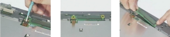
12. Disconnect touchpad FFC from the touch pad.
13. Remove the touchpad bracket as the pictures show. Please see the yellow arrows.
13. Remove the touchpad bracket as the pictures show. Please see the yellow arrows.

14. Remove the touchpad.
15. Disconnect the touchpad FFC and then remove it.
15. Disconnect the touchpad FFC and then remove it.

16. Remove the two screws that hold switchboard on the
logic upper. One is on the right; the other is on the
left.
17. Disconnect the audio board FPC from the switchboard.
18. Disconnect the switchboard FPC.
19. These are complete steps for logic upper disassembly.
left.
17. Disconnect the audio board FPC from the switchboard.
18. Disconnect the switchboard FPC.
19. These are complete steps for logic upper disassembly.

Disassembling the LCD Module-15 Inch
1. First remove the two screw pads then remove the two screws.
2. Disattach the LCD bezel carefully. Please note that you have to push forward at the two indentations.
3. Unscrew the two screws then remove the latch.
1. First remove the two screw pads then remove the two screws.
2. Disattach the LCD bezel carefully. Please note that you have to push forward at the two indentations.
3. Unscrew the two screws then remove the latch.

4. Unscrew the two screws on the inverter board.
5. Remove the four screws holding the right and left hinges. There are two screws on each side.
6. Remove the right and the left hinge.
5. Remove the four screws holding the right and left hinges. There are two screws on each side.
6. Remove the right and the left hinge.

7. Dettach the EMI tape and then remove LCD from the
cover carefully.
8. Disconnect the inverter board from LCD FPC.
9. Disconnect the LCD power connector.
8. Disconnect the inverter board from LCD FPC.
9. Disconnect the LCD power connector.

10. Disconnect the LCD FPC.
11. Unscrew the eight screws on the brackets. There are four on each side then remove the brackets.
11. Unscrew the eight screws on the brackets. There are four on each side then remove the brackets.
